Our Services
Control Panels
AMF25 Computerized Modular Control Panel for AMF Operation
I- Central Unit:
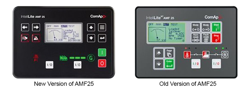
The central unit is an integrated controller for engine control in manual, automatic and remote start applications, featuring full genset monitoring and protection. It is equipped with a powerful graphic LCD display showing icons, symbols and bar graphs for intuitive operation together with high functionality set new standards in genset control.
Features:
To facilate the operator job supervision and intervention, the controller is equipped with the following:
1-Push Buttons for:
*OFF/AUTO/MANUAL/TEST Mode Selection *HORN RESET *FAULT RESET *MANUAL START *MANUAL STOP *MANUAL OPEN/CLOSE of Contactors. *SCROLL, PAGES & ENTER
2-Leds For:
*Mains available *Mains failure *Generator available *Generator failure *Mains contactor on *Generator contactor on
3-DispIay Menus:
At least 2 principal displays menus are available for: Measurements and Adjustment.
3.1- Measurements screens description:
Different screens selected by push buttons to display the following:
a-Main measure screen:
*Operation mode *Indication of active alarm *Status of the genset *Actual condition *RPM of the genset *Active power *Power factor *Timer-event counting time (e.g. prestart, cooling, transfer etc...)
B-Generator screen:
*Generator frequency *GenV1, V2 and V3 (triple barograph) *Gen Il, 12 and 13 (triple barograph)
c-Mains screen:
*Mains frequency *Mains (Voltage) VI, V2, V3 (triple barograph)
d-Analogue inputs screen:
*Oil pressure (Single barograph) *Water temperature (Single barograph) *Battery voltage (Single barograph)
e- Genset power screen:
*Active power (total and per phase) *Power factor (total and per phase)
f-Statistic screen:
*Kilowatt-hours KWh *Reactive power hours KVArh *Run hours *Number of starts *Next service time
g- Alarm list screen:
To display the following alarms when they come up: -Oil pressure, Water temperature and Fuel level warning and shutdown -Battery over/under voltage -Start fail -Generator voltage unbalance -Generator over/under voltage (3phases) -Generator over/under frequency (3phases) -Current unbalance -Over speed -Under speed -Emergency stop -GC failure -MC failure -Charging Alternator failure -Warning service time -Overload -Sensor failure -Mains over/under voltage (3phases) -Mains over/under frequency (3phases) -Phase sequence
3.2- Adjustment:
To allow:
*The setting and adjustment of all electrical and mechanical parameters of the genset and bus bars including all possible delay timers.
*The above listed alarm configuration with one of the following possibilities:
-Sensor fail -Warning -Unload -Slow stop -Shut down
*The configuration of the following parameters:
-Nominal power -Nominal current -Current ratio -Nominal voltage -Nominal RPM -Nominal frequency -Gear teeth -Prestart delay timer -Max crank timer -Crank pause timer -Number of crank attempts -Cooling timer -Next service timer -Horn timer -Over speed -Protection delay -Oil pressure alarm -Water temperature alarm -Fuel level alarm -Over/under battery charger -Generator overload -Current short circuit -Generator current unbalance -Generator over/under voltage -Generator unbalance voltage -Generator over/under frequency -Generator over/under voltage -Generator unbalance voltage -Generator over/under frequency -Mains over/under voltage -Mains over/under frequency -All delays timers
II-Communication:
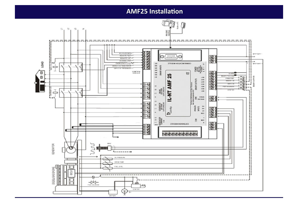
RS232 is incorporated in the controller and connected to modem extension unit for multiple engine control and PC communication.
The controller is able to support all kind of remote communications such as can bus, telephone line (Analogue modem) and mobile phone (GSM modem).
III-Software:
1) LiteEdit PC Tool for Configuration and Supervision of IL Controllers
General information
*To be used with InteliLite controllers
*Remote control and monitoring, parameters adjustment
*Configuration, programming
*Support of electronic engines
*Connection via RS232 or modem
2) WinScope Controllers' Monitoring Software
General information
*Monitoring and archiving of ComAp controllers' parameters and values
*View of actual/historic trends in the controller
*Supports connection to all Inteli-line controllers
*Enables parameter setting of ECON and INCON controllers
IV-options:
To be fitted to the central unit if required at additional prices;
1) IG-IOM Input/Output Module
General information
*Input and output extension module
*8 binary and 4 analog inputs
*8 binary and 1 analog output
*Connection to controller with standard IOM cable (2 meters)
*Not galvanic separated
2) IGL-RA15 Remote Annunciator
General information
*Extension signaling unit for remote gen-set controllers
*15 LEDs with configurable colors red-green-yellow
*Customizable labels
*Local horn output
*Lamp test function
*Connected via CAN bus, max distance 200m from the controller
3) IGS-PTM Input/Output Module
General information
*Input and output extension module
*8 binary and 4 analog inputs
*8 binary and 1 analog output
*Measures values from Pt100 and NilOO sensors
*Analog inputs have maximum resistance range 0-250 Ohms, voltage range 0-100mV, current range 0-20mA selectable via jumper
4) I-RD Remote Display
General information
*Remote signaling and control unit with RS232 interface
*For InteliLite gen-set controllers
*Gen-set can be controlled from I-RD as well as from master controller
*I-RD screens display the same as master controller
*Buttons and LEDs have the same function
5) I-LBA Low Battery Adaptor
General information
Module connected between 12 V DC battery and controller power terminals to support controller battery voltage dips. Keeps the controller operating during battery voltage drop, e.g. while the engine is cranking Remark: Direct communication with electronic control unit (ECU or ECM)


