Our Services
Syncrhonising Systems
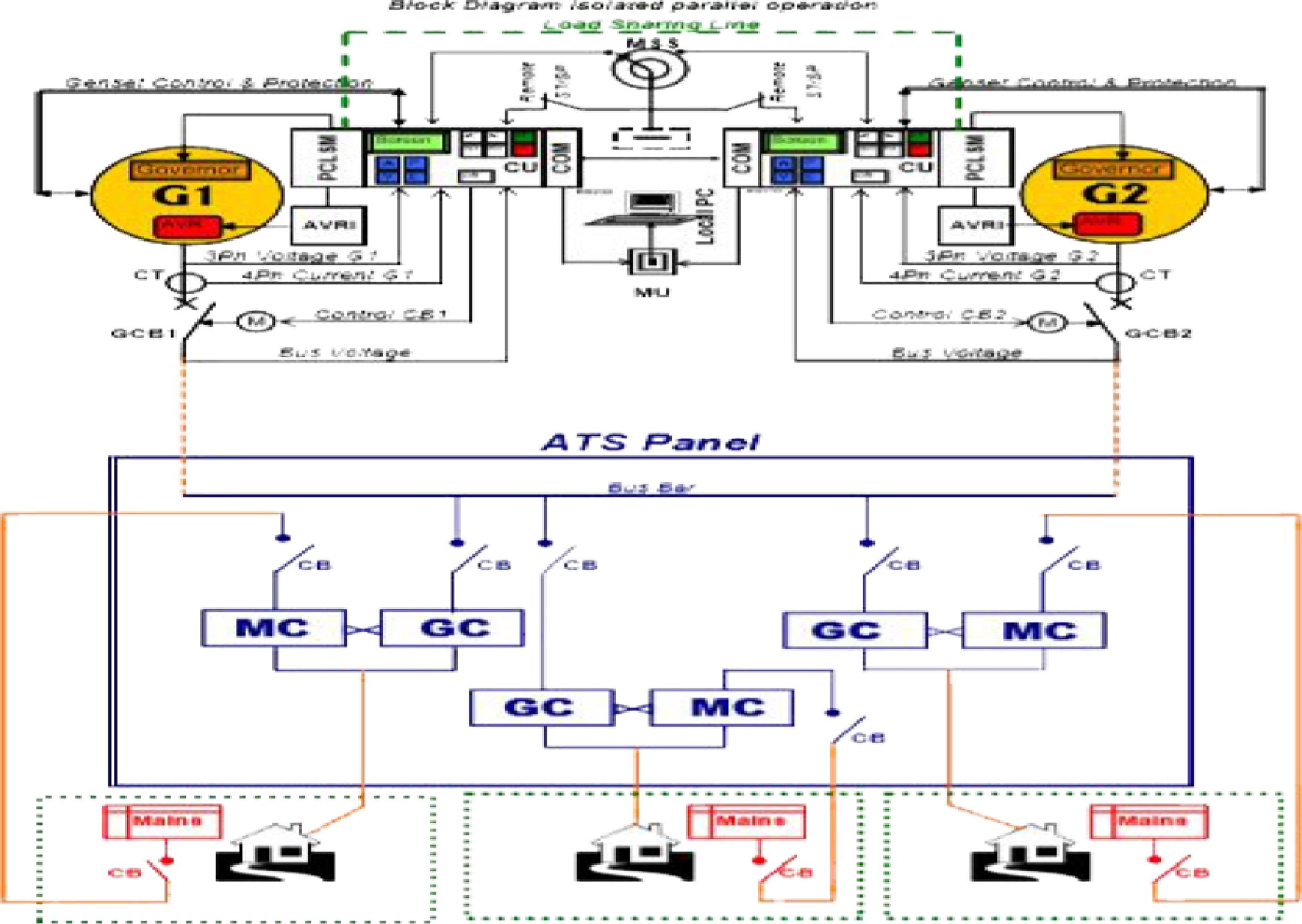
Engine Mounted Computerized Modular ControlPanel with built Automatic Paralleling
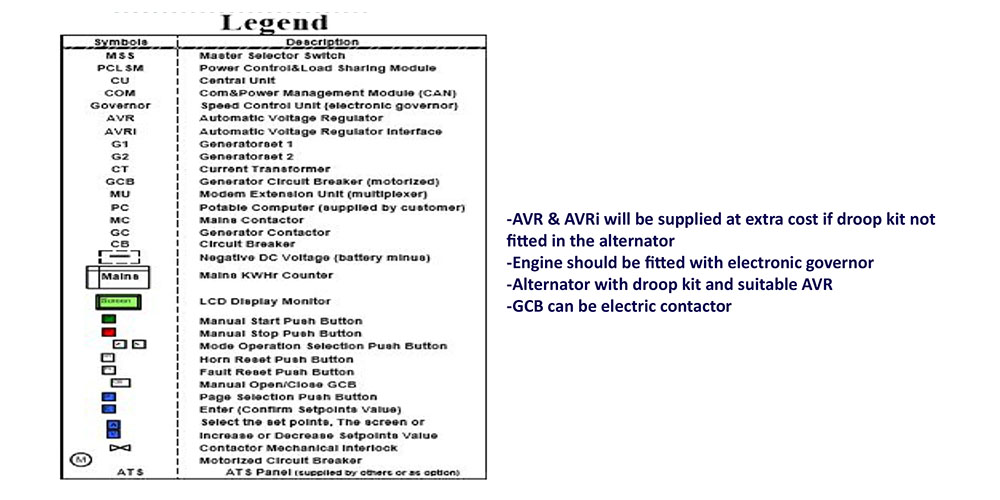
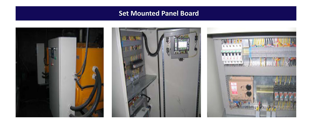
Set mounted in a separate cubicle IP40. (The Only controller in the world having all features of protection, start/stop, monitoring, history file, synchronizing, load sharing, load shedding and load management built-in) The complete modular controller will consist of the following:
Central Unit:
The central unit is an integrated controller for engine control in manual, automatic and remote start applications, featuring full genset monitoring and protection. It is equipped with a powerful graphic LCD display showing icons, symbols and bar graphs for intuitive operation together with high functionality set new standards in genset control
Features:
To facilate the operator job supervision and intervention, the controller is equipped with the following:
1-Push Buttons for:
*OFF/AUTO/MANUAL Mode Selection *HORN RESET *FAULT RESET *MANUAL START *MANUAL STOP *MANUAL OPEN/CLOSE (Synchronizer) of generator circuit breaker.
2-Leds For:
* Bus voltage present *Bus failure *Generator voltage present *Flashing led for gernset failure *Generator circuit breaker on
3-DispIay Menus:
At least 3 principal displays menus are available for: Measurements, Adjustment and History.
3.1- Measurements screens description:
Different screens selected by push buttons to display the following:
a- Main measure screen:
*Operation mode*lndication of active alarm*Status of the genset*Actual condition*RPM of the genset *Active power *Power factor* Timer-event counting time (e.g. prestart, cooling, transfer etc...)
b- Generator screen:
*Generator frequency *Engine speed (single barograph)*GenV1, V2 and V3 (triple barograph)*Gen Il, 12 and 13 (triple barograph)
c- Bus-screen:
*Earth fault current *Bus frequency *Bus (Voltage) Vbl, Vb2, Vb3 (triple barograph)
d- Analogue inputs screen: *Oil pressure (Single barograph) *Water temperature (Single barograph)
*Fuel level (Single barograph) *Battery voltage (Single barograph)
e- Genset power screen:
*Active power (total and per phase) *Power factor (total and per phase) *Reactive power KVAr (total and per phase) *Apparent power (total and per phase)
f-Statistic screen:
*Kilowatt-hours KWh (active energy) *Reactive power hours KVArh (reactive energy) *Run hours *Number of starts *Next service time
g- Synchronoscope screen:
*The synchronoscope will measure and display: *The angle between the generator and bus voltage. *The slip frequency. *The genset and bus voltage.
h- Power Management screen:
*Engine priority *Total available power *Total run power *Active reserve
i- Alarm list screen:
To display the following alarms when they come up:
-GCB failure -Overload -Over current -Short circuit (3 phases) -Current unbalance -Generator voltage unbalance
-Generator over/under voltage (3phases) -Generator over/under frequency (3phases) -Reverse power -Earth fault
-Bus measurement error -Over speed -Under speed -Start fail -Wrong phase sequence -Inverted phase polarity
-GCB fails detection -Sensor failure -Load sharing module failure -Bus voltage error detection
3.2- Adjustment:
To allow:
*The setting and adjustment of all electrical and mechanical parameters of the genset and bus bars including all possible delay timers.
*The above listed alarm configuration with one of the following possibilities: -Sensor fail -Warning -Unload -Slow stop -Shut down -History record
*The configuration of the following parameters:
-Nominal power -Nominal current -Current ratio -Earth fault current -Nominal voltage -Nominal RPM -Nominal frequency -Gear teeth -Prestart delay timer -Max crank timer -Crank pause timer -Number of crank attempts -Cooling timer -Next service timer -Horn timer -Over speed -Protection delay -Oil pressure alarm -Water temperature alarm -Fuel level alarm -Over/under battery charger -Generator overload -Current short circuit -Generator current unbalance -Generator over/under voltage -Generator unbalance voltage -Generator over/under frequency -Reverse power -Voltage window between generator & bus -Phase window between generator & bus -Level of speed governor voltage output -Synchro time out -Load shedding
3.3- History file:
The history file will store the record of each important event indicating at least:
I-The event specification -Time and date of the historical event -Generator power, cos@, voltage, frequency, current, speed -Bus voltage and frequency -Oil pressure -Water temperature
II-Power control load sharing module:
Connected directly to the central unit to allow:
*Automatic synchronizing *Reverse synchronizing *Load control including ramping *Power factor, import/export control *Earth fault protection *Analogue outputs for AVR and electronic speed governor *Analogue isochronous load sharing line between gensets
III-Power management:
Connected by can bus interface for:
-Interconnection of central unit gensets controllers -Optimizing the number of running engines -Interface to supervision system
